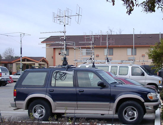
 This photo shows the antennas on three rover vehicles the morning after
the January, 2004 VHF SS contest. All of the antennas took hits during
the contest, tangling with at least one tree each. The 3-element
144, 222 and 432 MHz triband quads are atop rotating masts, with antennas
for higher frequencies below them.
This photo shows the antennas on three rover vehicles the morning after
the January, 2004 VHF SS contest. All of the antennas took hits during
the contest, tangling with at least one tree each. The 3-element
144, 222 and 432 MHz triband quads are atop rotating masts, with antennas
for higher frequencies below them.
A small VHF/UHF quad antenna
The small 3-element VHF/UHF cubical quad antennas
that were used by N6MU, N6MI and N6NB for their three-vehicle rover expedition
of January, 2004 have attracted considerable interest. In his article
about the three rover stations on Eham.Net, Steve Katz, WB2WIK,
suggested going into business manufacturing them. That isn't feasible,
but here is a description of the antenna, which was designed empirically
on a home antenna range using the methods described elsewhere on this website.
The triband quad is built on a 36" boom made
of 3/4" square hardwood dowel. The 144/222 MHz spreaders are 1/2"
square dowel. The 432 MHz elements are mounted on Plexiglas (tm)
spreaders. The elements are made of #12 TW solid (covered) copper
wire. If THHN type wire is used, it may be necessary to make the
elements slightly longer than the dimensions given here. These dimensions
are for the SSB/CW portion of each band. They may be scaled mathematically
to other parts of the bands.
The element dimensions are as follows:
144 MHz reflector, 87" loop; 144 driven element, 82" loop (with a SO-239
or type-N connector in the center of the bottom), 144 director, 76 1/2"
loop; 222 MHz reflector, 56 3/8" loop (on the same spreaders as the 144
MHz driven element); 222 MHz driven element, 53 1/2" (on same spreaders
as 144 MHz director), 222 MHz director, 50 1/2"; 432 reflector, 28 3/8"
loop; 432 driven element, 27" loop; and 432 director, 25 1/2" loop.
The inter-element spacing is: 144 R
to DE, 15 1/2", 144 DE/222 R to 432 R, 8 1/2", 432 R to 144 D/222 DE, 2
3/4", 144 D/222 DE to 432 DE, 3 1/2", 432 DE to 222/432 D, 5".
The antenna appears to have 7-8 dB. gain over
a dipole at its center frequency on each band, with a 15-20 dB. front-to-back
ratio. That is considerably less gain than a longer Quagi or Yagi
would exhibit, but dramatically more than an omnidirectional loop had in
side-by-side comparison tests on an antenna range. On the range,
a number of other designs were tested. It was determined that the
elements for 222 and 432 could be interlaced with the 144 MHz elements
as shown here without serious performance degradation. However, moving
the 144 MHz director any further forward, or moving the 222/432 elements
further back, reduced the gain by 3-4 dB.
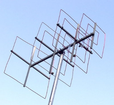 For
this demonstration photo, the three feedlines have been removed so the
antenna itself can be seen better. Note that this particular quad
has separate Plexiglas (tm) spreaders only for the 432 MHz reflector and
driven element. The 432 director shares a hardwood spreader with
the 222 MHz director. This arrangement reduces the gain on 432 by
a small amount. This photo
was taken after the antenna was straightened following a 1,300-mile road
trip. For
this demonstration photo, the three feedlines have been removed so the
antenna itself can be seen better. Note that this particular quad
has separate Plexiglas (tm) spreaders only for the 432 MHz reflector and
driven element. The 432 director shares a hardwood spreader with
the 222 MHz director. This arrangement reduces the gain on 432 by
a small amount. This photo
was taken after the antenna was straightened following a 1,300-mile road
trip.
<return to N6NB page>
|